 and the sensitivity were both adjusted to give the best
possible output from the Plessey algorithm.
The results of testing this corner finder are now shown and discussed.
Firstly, the output of SUSAN given the test image (shown earlier in
Figure 10) is shown, in Figure 20.
Compare this with Figure 21, the output from the
Plessey corner finder, described earlier. The spatial smoothing scale
 and the sensitivity were both adjusted to give the best
possible output from the Plessey algorithm.
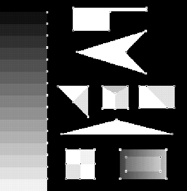
Figure 20: Output of the SUSAN ``corner'' finder (t=10) given the test
image.
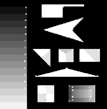
Figure 21: Output of the Plessey ``corner'' finder ( =2.0) given
the test image.
The accurate localization and reliability of the SUSAN algorithm is apparent; it does all it is expected to do. The inaccuracies and false positives of the Plessey corner finder, even at simple two region corners, are visible. This is fully explained in [62]. With respect to speed, SUSAN took 0.3 seconds to process this picture on a single Sun SPARC-2 processor; the Plessey corner finder took 3.5 seconds.
The SUSAN algorithm has also been tested with respect to its sensitivity to noise. The results are excellent; the quality of its output (both the reliability and localization) degrades far less quickly than other algorithms tested as noise in the image is increased. The test image used was the same as the noisy image previously used to test edge finders. The outputs of SUSAN and the Plessey corner finder are shown in Figures 22 and 23 respectively.
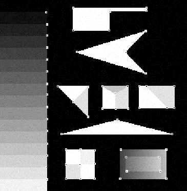
Figure 22: Output of the SUSAN ``corner'' finder (t=10) given
the test image with Gaussian noise of minimum SNR=5 added.
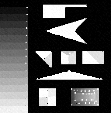
Figure 23: Output of the Plessey ``corner'' finder ( =2.0)
given the test image with Gaussian noise of minimum SNR=5 added.
To test the SUSAN corner detector's sensitivity to both corner
orientation and noise, a test described by Haralick in
[24] has been used. Here 9 squares of brightness 175
greylevels and size 20 by 20 pixels are placed on a background of
brightness 75 greylevels. The squares are drawn with orientations
ranging from  to
to  in
in  increments. Then Gaussian noise of standard deviation 10 is added to
the image. The outputs of SUSAN and the Plessey corner finder given
this image are shown in Figures 24
and 25 respectively.
increments. Then Gaussian noise of standard deviation 10 is added to
the image. The outputs of SUSAN and the Plessey corner finder given
this image are shown in Figures 24
and 25 respectively.![]()
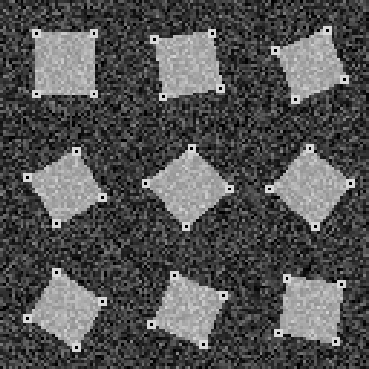
Figure 24: Output of the SUSAN ``corner'' finder (t=60)
given the orientation test image with Gaussian noise of standard
deviation 10 added.
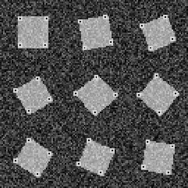
Figure 25: Output of the Plessey ``corner'' finder
( =2.0) given the orientation test image with Gaussian noise of
standard deviation 10 added.
The parameters of the Plessey corner finder were adjusted to give the best results. In [24] this image is used to test the Kitchen-Rosenfeld and Dreschler-Nagel corner detectors, and the best facet model-based detector of Zuniga and Haralick. The results show that both the SUSAN and Plessey detectors perform better than the three investigated in [24], which either do not detect all of the corners, or produce a large number of false positives. It is not surprising that the Plessey detector performs well, as one of the known strengths of the Plessey algorithm is its detection reliability. Indeed, it was designed to have this particular quality. However, as already noted, the SUSAN detector finds the corners with much greater accuracy.
Two examples of the output of SUSAN given real images are shown in Figures 26 and 27.
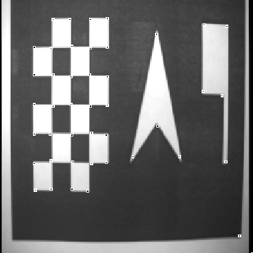
Figure 26: Output of the SUSAN ``corner'' finder (t=25) given a
real test image. The image was created by laser printing a synthetic
test image and then digitizing it using a video camera.

Figure 27: Output of the SUSAN ``corner'' finder
(t=25) given a real image captured by video camera.
Finally, the stability of SUSAN has also been tested. Initially this was done by running it on several (typically 10) images taken in succession from a moving video camera. The output can be viewed (in a short video created by running the 10 frames, with corners marked, forwards and backwards on the computer screen) by eye to judge how much ``flicker'' there is amongst the corners. The corners should be seen to travel smoothly with the scene and not appear or disappear, except at the edges of the screen or at occluding boundaries. There will always be some flicker of the corners, mostly due to the quantization of the image. The Plessey corner finder has excellent stability. This makes it appropriate for use in systems where high accuracy is not necessary. Unfortunately, the good stability is basically won at the cost of its speed and localization accuracy. The SUSAN corner finder gave good results; the stability looked similar to the Plessey algorithm, and was as good or better than the other corner finders tested.
For a more quantitative test of stability, the output from 10 consecutive frames was used as the first stage of the DROID three dimensional vision system developed by Plessey (see [25] and [10]). This program tracks corners through time in order to reconstruct a three dimensional description of the world. The results obtained when the Plessey corner finder was used were compared with those obtained when SUSAN was used. Several different sequences were tested. Some sequences gave slightly better three dimensional output data when using the SUSAN algorithm, and the rest gave similar results with both algorithms. For example, Figures 28 and 29 show
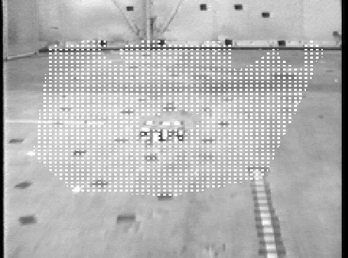
Figure 28: A least
squares plane fitted to the data output from DROID using the SUSAN
``corner'' finder as the ``front end'' -- the shaded area corresponds
to parts of the scene which lie on (or very near) the plane.
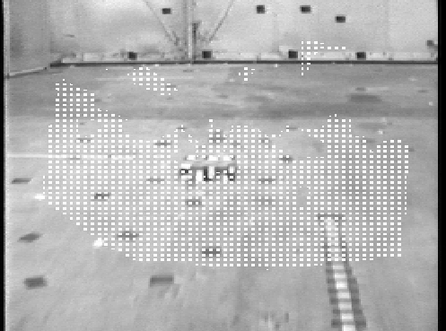
Figure 29: A
least squares plane fitted to the data output from DROID using the
original (Plessey) ``corner'' finder as the ``front end''.
scene 9 of a short sequence in which a small box (5 cm high) is placed on a fairly flat floor. DROID has been run on the 9 frames, and the output data has been used by a program designed to find the unobstructed ground plane. This program fits a least squares plane to the list of three dimensional points given by DROID, and then recomputes the plane, ignoring upper outliers, until convergence. From these pictures it can be seen that in both cases the small box was correctly identified as an obstacle, but the ground plane found when using the SUSAN algorithm did not break up as it did when using the Plessey algorithm. Note also that the driveable region created when using the Plessey corner finder goes further up the end wall than the driveable region created by using the SUSAN detector. These observations suggest that in this example the quality of the data was slightly better when using the SUSAN ``corner'' finder. This investigation was originally fully reported in [61], where the spatial ``resolution'' of DROID was found using the Plessey corner finder. Since then, as indicated above, the resolution has been improved by a factor of approximately two, by using the SUSAN ``corner'' detector as a front end.
In these tests, SUSAN ran on average 10 times faster than the Plessey algorithm. (This factor is quite important, as the Plessey corner detector takes about 85% of the total running time of the complete DROID program.)
Finally, as another test of its stability and general suitability for real applications, SUSAN has been used in the ASSET motion segmentation system, described in [65], with excellent results.