Image Based Shimming
This method uses an automated image based shimming programme.
Selecting 3d Image Shim from the Scanning Page initiates an asymmetric spin echo imaging sequence and then uses a mainly automated IDL programme to determine the shim values that are needed to correct for the determined field inhomogeneities.
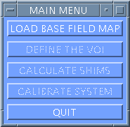
Once the imaging sequence is completed the window in Figure 1 appears.

Figure 1. Main Shimcalc menu.
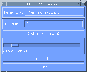
Press LOAD BASE DATA to bring up the Load window.
Load Base Data

Figure 2. Shimcalc Load menu.
The Directory and Filename will contain the pathway and Filename of the data just acquired.
The default of OXFORD 3T (HEAD) should be displayed if you are using the head gradient coil.
SMOOTH VALUE allows you to set the width (in pixels) of the spatial Gaussian smoothing filter. The sliding cursor bar can be moved using the left-hand mouse. This is ordinarily set on 2 pixels.
To leave the programme at this point select CANCEL
To continue, using the parameters set, select EXECUTE. The programme will now load the raw data.
The main menu (shown in Figure 1) is again displayed on the left of the screen.
Define VOI

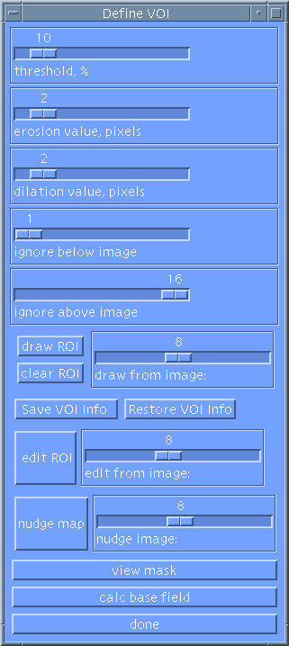
Figure 3. Shimcalc Define VOI menu.
Select DEFINE THE VOI to display the VOI window (shown in Fig. 3) which allows you to select a mask for the area in which the field will be calculated and also performs the phase bounce unwrapping procedure.
The aim is for the unwrapped field map to be smooth with no sharp transitions between bright and dark regions (indicating phase bounces that have not been unwrapped by the phase unwrapping procedure).
There are several methods that can be chosen to help achieve this using the Define VOI window.
THRESHOLD, %: This option enables you to threshold out noise by sliding the scale with the left-hand mouse to a required percentage value. The programme will then ignore any signal below the set threshold. 10% is a good starting value.
EROSION/DILATION VALUE, PIXEL: These scales allow you to either erode or dilate the mask to remove extraneous signal and obtain a mask without holes in it.
IGNORE BELOW IMAGE/IGNORE ABOVE IMAGE: A mask can be produced that ignores unwanted images at the top or bottom of the imaging stack. If all images are required then set the scales to the lowest and highest slice respectively.
DRAW ROI: This option allows you to draw a region of interest on an image and to include everything within the ROI in the mask. First, using the left-hand mouse, set the draw from image scale to the image number you want to use. Then, again using the left-hand mouse button, click on points on the image that will be joined by a line and determine a region of interest.
CLEAR ROI: will clear the region of interest from the image.
SAVE VOI INFO: Saves the VOI to a scratch file on disk.
RESTORE VOI INFO: Recalls the VOI from the scratch file on disk.
EDIT ROI: This option allows you to draw a region of interest on an image and to edit out everything within that region from the mask. First, using the left-hand mouse, set the edit from image scale to the image number you want to use. Then, again using the left-hand mouse, click on points on the points that you wish to form the boundary of the regions to be edited out of the mask. Complete the ROI using the right-hand mouse button.
NUDGE MAP: This option can be used to help unwrap phase bounces by "nudging" the image through increasing or decreasing phase wraps. First, using the left-hand mouse, set the nudge image scale to the image number you want to nudge. Then use either the Left or the Right-hand mouse buttons to nudge the image negatively or positively through a 2pi phase bounce.
VIEW MASK: Once you have set the above options you can check the results using this option.
CALC BASE FIELD: Allows you to compute and view the base field map. The resultant images will be displayed in the right hand window of the screen. The Standard Deviation shown at the bottom of this screen will be a measure of the pre-shim linewidth. If you still see phase bounces (sharp transitions between bright and dark in the image) then you should repeat the above steps until you are satisfied with the final field map. The shims will not compute properly if the field map is corrupted by phase bounces.
When the field map has completed, click on the DONE button to return to the Main Shimcalc Menu.
The last stage is to CALCULATE SHIMS. By selecting this button the programme will use the field map produced by the previous steps to calculate shim current values that will compensate for the field inhomogeneities.
Finally, press QUIT to exit. Another prompt will come up asking if you want to REALLY QUIT?.
To determine how good the shim is you will need to check the linewidth of water (measured as the FWHM value in Hertz). This linewidth should be a value as small as possible below 30Hz for any imaging sequence (and in particular for EPI).
To obtain a linewidth measure, press Auto Centre Frequency from the Auto Prescan page. A water spectrum will be acquired and displayed in the interactive graphical window. The linewidth, in Hertz, will be displayed in the Varian window at the top left of the scanning console.