This guidance was written prior to the February 27, 1997 implementation of FDA's Good Guidance Practices, GGP's. It does not create or confer rights for or on any person and does not operate to bind FDA or the public. An alternative approach may be used if such approach satisfies the requirements of the applicable statute, regulations, or both. This guidance will be updated in the next revision to include the standard elements of GGP's
Medical Device Interactions with
Magnetic Resonance Imaging Systems
The Federal Register notice reopening the comment period for this document was published May 22, 1997, and extends the comment period to August 20, 1997. Comments and suggestions regarding this draft document should be submitted
to Marlene Skopec, Office of Science and Technology, HFZ-133,
12721 Twinbrook Pkwy, Rockville, MD 20852. Comments and suggestions
received after August 20, 1997, may not be acted upon by the Agency until
the document is next revised or updated. For questions regarding
this draft document, contact Marlene Skopec at (301) 443-3840.
| 1.0 | Scope/Purpose | 1 |
| 2.0 | Definitions | 2 |
| 3.0 | Introduction and Overview of Medical Device Concerns | 4 |
| Table 1: MR Environment Medical Device Concerns | 5 | |
| Table 2: Effect of Medical Device on Operation of MR Scanner | 5 | |
| 4.0 | Components of MRI and Effects on Medical Devices | 6 |
| 4.1 The Static Magnetic Field and Spatial Gradient | 6 | |
| 4.2 Pulsed Gradient Magnetic Fields | 8 | |
| 4.3 Pulsed Radio Frequency Fields | 8 | |
| 4.4 Image Artifacts and Noise | 10 | |
| 5.0 | Basic MR Theory | 11 |
| 6.0 | Labeling | 15 |
| 7.0 | General Notes on Testing for MR Compatibility | 18 |
| 8.0 | References | 19 |
| Appendix A: | SOME THOUGHTS ON CRITERIA FOR DEVICES TO BE USED IN THE MR ENVIRONMENT (DRAFT) | 20 |
The purpose of this document is two-fold.
It should serve to sensitize medical device reviewers to the meaning
and ramifications of MR safety or MR compatibility claims. It
will also provide a background of MR theory and the effect the
MR environment may have on medical devices. This is intended
to serve as a general background document on medical device interactions
in magnetic resonance imaging systems. It is not intended to
replace documents created that address specific devices or device
areas. Questions or concerns regarding this document may be directed
to Marlene Skopec in OST/DPS/EPB at 443-3840 or by electronic
mail at MDS.
Reviewers should direct phone calls from health
care professionals or consumers who wish to make FDA aware of
concerns they have regarding device interactions or other types
of problems associated with the magnetic resonance imaging environment
to FDA's
voluntary MedWatch program at
1-800-FDA-1088. If manufacturers, user facility
personnel or device distributors subject to mandatory reporting
requirements request a determination of whether or not an event
is required to be reported under the Medical Device Reporting
Regulations, they should be referred to the Office of Surveillance
and Biometrics, Division of Surveillance Systems, MDR Policy/Guidance
Group at
(301) 594-2735.
2.0 Definitions
* note: 1 tesla = 10,000 gauss
The "MR Environment" includes anywhere in the MR procedure room, including the center of the bore of the MR scanner.
* The use of the terms, "MR
Compatible"
and "MR
Safe"
without specification of the MR environment to which the device
was tested should be avoided since interpretation of these claims
may vary and are difficult to substantiate rigorously. Statements
such as "intended
for use in the MR environment"
or similar claims along with appropriate
qualifying information are preferred (i.e. test conditions should
be specifically stated). *
Unlike x-ray based medical diagnostic techniques
such as computed tomography, magnetic resonance imaging (MRI)
and spectroscopy are techniques which do not employ ionizing radiation.
As such, it is considered to be less hazardous than other x-ray
imaging techniques. In addition, since x rays can only discriminate
different tissues by electron density, which does not vary greatly
between soft tissues, the injection of contrast media is often
necessary. In MRI, however, there are a number of tissue specific
parameters which can affect magnetic resonance (MR) signals.
One of the most important advantages of MRI is its capacity for
displaying soft tissue contrast. An example of this capacity
is the discrimination between the gray and white matter of the
brain that can be accomplished with MRI. Image contrast can be
tailored to the specific clinical application so that specific
types of pathology are emphasized. In addition, since MRI is
unobstructed by bone, it is especially beneficial in imaging of
the brain and spinal cord. MRI also has the unique ability to
acquire images in numerous planes without repositioning the patient.
Three-dimensional recreations of anatomic structure can be obtained.
These characteristics render MRI a very effective and important
tool for soft tissue imaging.
Hazards
The potential benefits of MRI are numerous; however, there are hazards intrinsic to the MR environment which must be acknowledged and respected. These hazards may be attributed to one or to a combination of the three main components that make up the MR environment: a strong static magnetic field including its associated spatial gradient, pulsed gradient magnetic fields, and pulsed radio frequency (RF) fields. For a properly operating system, the hazards associated with direct interactions of these fields and the body are negligible. It is the interactions of these fields with medical devices placed within the fields that creates concerns for safety. Each of the component fields is described in detail along with relevant documented cases of adverse events in Section 4. There are numerous documented cases of mishaps in the MR environment that have resulted in injury and even death in a few cases. Those listed are just a sampling of adverse events that are documented in the Medical Device Reports (MDR) and Problem Reporting Program (PRP) systems. It is likely that many adverse incidents occur, but are not reported.
Another aspect of introducing a medical device
into the MR environment is the effect its presence and operation
may have on proper functioning of the MR scanner. Concerns related
to this aspect including image artifact and noise are also addressed
greater detail in Section 4.
The tables on this page provide a summary of
the hazards and concerns related to medical devices in the MR
environment.
Component of MR Environment | Medical Device Concern | Potential Adverse Effect |
Static Magnetic Field (always on) | Rotational force (torque) on object | Tearing of tissues Rotation of object in order to align with field |
Static Magnetic Field Spatial Gradient (always on) | Translational force on object | Tearing of tissues Acceleration of object into bore of magnet "missile effect" |
|
Gradient Magnetic Field (pulsed during imaging) | Induced currents due to dB/dt | Device malfunction or failure |
Radio Frequency Field (pulsed during imaging) | RF induced currents resulting in heating | Patient burns (thermal and electrical) |
Radio Frequency Field (pulsed during imaging) | Electromagnetic Interference- active device | Device malfunctions Induced noise (monitoring devices) |
Excessive Electromagnetic Emissions from Medical Device | Poor quality images Low signal to noise ratio |
Presence of Implant or Surface Electrode in or near Imaging Field of View | Image degradation (distortion, artifact, etc) Signal voids in image |
4.1 The Static Magnetic Field and Spatial
Gradient
An intense static magnetic field is a component
of the MR environment which is always present even when the scanner
is not imaging. This static magnetic field is typically between
0.2 and 2.0 tesla (5,000 to 20,000 Gauss) measured in the center
of the magnet bore. Current state-of-the-art technology is pushing
this upper limit to 4 or 5 tesla in research MRI systems. This
is up to 100,000 times the magnetic field strength of the earth.
This strong magnetic field strength drops off rapidly with distance
away from the magnet, producing a large spatial gradient. As
a result of this large gradient, magnetizable objects introduced
into the field are accelerated and can quickly become dangerous
projectiles. Imagine a pair of sharp scissors flying through
the air pulled into the magnet bore (see MDRs listed below).
In addition, just as magnetic material aligns
itself with the poles of a permanent bar magnet or a compass needle
aligns itself with the earth's
magnetic field, certain objects introduced into the MR environment
will exhibit similar behavior. When brought near the magnet, these
objects may be subjected to a torque which acts to align it with
the magnetic field. This motion can be especially hazardous,
for certain implanted medical devices. In short, the static magnetic
field can induce a torque on an object whereas the associated
spatial gradient can exert a translational force on the object.
The magnitude of these effects is dependent on the geometry and
mass of the object, as well as the characteristics of the MR system's
magnetic field.
Therefore, patients with certain implanted devices, such as many types of intracranial aneurysm clips, are contraindicated from MR imaging since the torque and displacement forces produced on the device can result in the tearing of soft tissues. In fact, there has been at least one death recorded as a result of movement of an aneurysm clip. When the event occurred, the patient was in the process of being moved in towards the magnet, but had not yet entered the magnet bore. Other implants, such as certain cardiac pacemakers are known to function erratically even in relatively weak magnetic fields. In device labeling for pacemakers, MRI is listed as a contraindication. Individuals with implanted pacemakers, whether or not pacemaker dependent, are contraindicated from entering the MR procedures room or coming within the 5 gauss line around the scanner. In general, persons with any type of electrically, magnetically, or mechanically activated implants (pacemakers, neurostimulators, infusion pumps, etc.), should remain outside the 5 gauss line.
It is important to note that the working of
a material (e.g., machining, molding, bending) may significantly
alter its magnetic properties. This change can be so significant
that while the bulk material may be initially magnetically inert,
once it is formed into a medical device, it may experience torque
and translational forces significant enough present a safety hazard
when introduced in the MR environment. Therefore, all testing
of devices for immunity to the strong static magnetic fields should
be conducted on the device in its finished form. Quality assurance
is especially important in order to insure that the behavior of
a device in the MR environment does not vary significantly from
item to item.
* These events may also be attributed to the
pulsed RF fields.
4.2 Pulsed Gradient Magnetic Fields
Another component of the MR environment is
a pulsed gradient magnetic field that is used for signal localization.
When this gradient magnetic field is applied, the magnetic field
intensity changes rapidly, giving rise to a time-varying magnetic
field. During the rise time of the magnetic field, a voltage
is induced in an electrical conductor, even when it is stationary
in the field. However, in most MRI systems, the currents induced
by the pulsed magnetic gradient field are about 1,000 times smaller
than those induced by the pulsed RF component and are therefore
not of great concern with regard to thermal injuries.1
Major concerns with the pulsed gradient fields are biological
effects including electrical nerve stimulation and the generation
of light flashes (magnetophosphenes) that may result from a slight
torque exerted on the retinal cones. Current FDA guidance limits
the Time Rate of Change of Magnetic Field (dB/dt) to levels which
do not result in painful peripheral nerve stimulation.
4.3 Pulsed Radio Frequency Fields
A third main component of the MR environment
is the pulsed radio frequency (RF) magnetic fields which is used
to elicit MR signals from tissue. With regard to biological effects,
one main concern with this component of MR is the production of
heat in tissue. The rate at which RF energy is deposited in tissue
is defined as the specific absorption rate (SAR) which is measured
in units of watts per kilogram (W/kg). Current FDA guidance limits
SAR whole body exposure to 4.0 W/kg for patients with normal thermoregulatory
function and 1.5 W/kg for all patients, regardless of their condition.
The duty cycle on the RF pulse during MR imaging is restricted
based on this SAR limit.
With regard to medical devices, electrical
currents may be induced in conductive metal implants, such as
skull plates, and hip prostheses. When conductive patient leads
are used during MR scanning, it is especially critical that no
loops are formed by the leads. Looped patient leads or devices
such as the halo device used for spinal immobilization can pick
up RF energy resulting in induced currents, heating of the material,
and as a result, potentially severe patient burns. To further
reduce the possibility of burns, it is recommended to thermally
insulate electrically conductive material in the bore of the magnet
from the patient using blankets or sheets.
* This event may also be attributed
to the static magnetic field.
4.4 Image Artifacts
and Noise
Image artifacts and RF noise can be caused
by the presence and/or operation of a medical device in the MR
environment. Artifacts can be caused by medical devices which
are in or near the imaging field of view (such as implants or
surface electrodes). Materials produce their own characteristic
static magnetic field that can perturb the relationship between
position and frequency essential to accurate image reconstruction.
If the object has a magnetic susceptibility that is significantly
different from that of tissue, distortion will result. Also,
an implant may exhibit an induced eddy current due to the incident
RF magnetic field, altering the RF field near the implant and
thereby causing distortion.
RF noise, which often appears as static on
the image, can be caused by a medical device located anywhere
in the MR procedure room. RF noise is a result of excessive electromagnetic
emissions from the medical device that interfere with the proper
operation of the MR scanner. Since the MR procedure room is shielded
from extraneous RF fields entering the room, operation of electromagnetically
noisy equipment outside the room does not typically affect the
MR scanner.
Primary concerns with image artifact and noise
include the production of a void where anatomical information
is needed as well as the production of artifacts that may be misdiagnosed
as pathology (see MDR below).
MDR-183091: Surgery was performed on a patient
based on an artifact present on an MR image (1/30/90).
In the nucleus of every atom, individual protons
and neutrons spin about an axis. This property, called spin angular
momentum, is the basis of nuclear magnetism. Since atomic nuclei
have charge, this spinning motion produces a magnetic moment along
the spin axis. In most nuclei, the particles are paired so that
the net magnetic properties cancel. However, if the number of
protons or neutrons is odd, complete cancellation is not possible.
Nuclei with an unpaired proton or neutron such as hydrogen 1,
carbon 13, and sodium 23, among others, exhibit a net magnetic
effect. The relative strength of this magnetic moment is a property
of the type of nucleus and therefore determines the MR detection
sensitivity. The hydrogen (1H) nucleus, which is highly
abundant in biological systems, has the strongest magnetic moment.
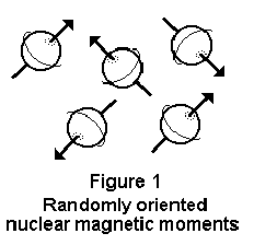
Since the individual magnetic moments (or axes
of spin) are randomly oriented, biological tissue does not normally
exhibit a net magnetization (Figure 1).2 However,
in the presence of an external static magnetic field, B0,
the individual magnetic moments tend to align either parallel
or antiparallel to the direction of the applied field, similar
to the way a permanent bar magnet will align itself with the field
or a compass needle aligns with the earth's
magnetic field.
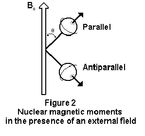
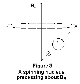
Since a parallel alignment to the field is the lower energy state, it is preferred and slightly more nuclei will align parallel rather than antiparallel to the field. As a result, the tissue will exhibit a net magnetization not unlike like that of a piece of iron in a magnetic field, although not as strong. The individual spins do not align exactly parallel to the applied field, but at an angle to it (Figure 2).2 Like a spinning top, the individual spins cause the moment to precess about the axis of B0 (Figure 3).2 The frequency with which the moment precesses is given by the Larmor equation shown below.
Y B0
= f
where B0 = strength of the applied magnetic field
Y = gyromagnetic ratio (related to the strength of the magnetic moment for the type of nuclei)
f = the frequency
of precession (Larmor frequency)
For the hydrogen atom Y
= 4257 Hz/Gauss. Therefore, at B0 = 1.5 Tesla (10,000
Gauss = 1 Tesla), the Larmor frequency is 63.855 MHz.
In order to create an MR signal which can be
detected, a resonance condition must be established. In other
words, there must exist a situation of alternating absorption
and dissipation of energy. In the external static magnetic field,
B0, nuclei can be shifted from the parallel to antiparallel
alignment by the application of radio frequency energy. Application
of radio frequency (RF) magnetic field at the Larmor frequency
results in energy absorption, while RF energy applied at other
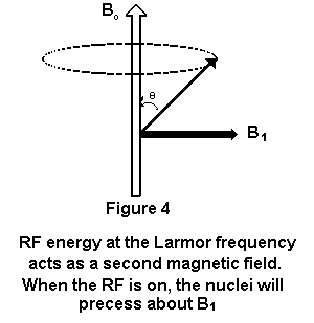
frequencies has no effect. If we
consider an RF magnetic field,
B1, applied perpendicular to B0, the system
will absorb energy and begin to precess about the B1
axis (Figure 4). 2
If the RF energy is pulsed, the net magnetization
is rotated to a certain angle away from the B0 axis.This angle is
referred to as the flip angle and is proportional
to the duration and amplitude of the RF pulse. Upon termination
of the RF pulse, the nuclei return to their original alignment
parallel to the applied static field and energy is emitted in
the form of a weak RF signal. The frequency of the emitted signal
depends on the strength of the applied static magnetic field as
well as the type of nuclei producing the signal. Detection and
analysis of this signal provide insight into the chemical composition
of the material. This process of alternating absorption and emission
of RF energy by the material is termed magnetic resonance
(MR).
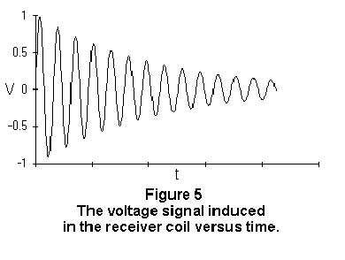
At the end of the applied RF pulse, the RF signal emitted by the material is at its maximum intensity. The signal intensity diminishes rapidly (within a few hundred milliseconds) as the higher energy state (the antiparallel state) is depopulated and the nuclei return to their original energy state. This RF signal is picked up by a receiver coil. The waveform of this signal is an exponentially damped sine wave and is called the free induction decay (Figure 5).2
In order to produce an image, each MR signal
must be referenced to a specific region of tissue. This is accomplished
by applying a gradient magnetic field in which the field strength
varies linearly with position. The gradient gradually varies
the magnetic field strength resulting in a corresponding shift
in the RF frequency needed to stimulate the tissue. Since emitted
RF signals will also demonstrate a shift in frequency, the excited
tissue from which the signals originated can be localized. Using
a computer-aided reconstruction program, similar to that used
in computed tomography, the signals attributed to individual volume
elements of tissue can be resolved and reconstructed into an image.
The most common method of image reconstruction is the two-dimensional
Fourier transform.
Note:
Judgement should be exercised in requesting
data for the substantiation of MR claims. A risk assessment considering
the potential outcomes of adverse interactions in the MR environment
should be constructed to help determine the need for and degree
of substantiation necessary for MRI claims. For example, certain
passive devices constructed entirely of polymers may not require
data to substantiate its suitability for use in the MR environment.
The attachment, "Some
Thoughts on Criteria for Devices to be Used in the MR Environment"
provides a list of concerns to consider in your evaluation. For
further assistance on specific issues, contact your division MR
Working Group Representative or other group member.
Substantiation of Claims
If a device is to be labeled MR Safe, the following information should be provided:
a) data demonstrating that when the device is introduced or used in the MR environment (i.e. the MR scan room) it does not pose an increased safety risk to the patient or other personnel or;
b) a scientifically based rationale for why
data are not necessary to prove the safety of the device in the
MR environment (for example, a passive device made entirely of
a polymer known to be nonreactive in strong magnetic fields).
If a device is to be labeled MR Compatible, the following information should be provided:
a) data demonstrating that when the device is introduced or used in the MR environment, it is MR safe, that it performs its intended function without performance degradation, and that it does not adversely affect the function of the MR scanner (e.g. no significant image artifacts or noise). Any image artifact or noise due to the medical device should be quantified (e.g., % volume affected, signal to noise ratio); or
b) a scientifically based rationale for why data are not necessary to prove the compatibility of the device in the MR environment (see example above).
Claims to include Test Conditions and Outcomes
Claims regarding MR Compatibility, or MR Safety,
including claims stating or implying that a device may be used
or brought into the MR environment, such as "intended
for use during MR imaging"
should be substantiated with supporting data. If supporting data
is not provided, the sponsor may provide a justification for why
this data is not necessary to support the claims (e.g., the device
is made entirely of a polymer having a susceptibility similar
to tissue). This information should include the following:
a Unless
the device is intended to be permanently attached to the floor
or to the structure of the MR scan room, the device should be
tested at the minimum distance from the magnet isocenter that
it may be physically positioned. If the device can physically
fit into the magnet bore, it should be tested in the bore. The
type of magnet used (shielded or unshielded) should be specified
since the magnetic field spatial gradient is larger in the shielded
case.
b The
manufacturer should locate the maximum spatial magnetic field
gradient for the MRI system employed and test the device at that
position when practical. The maximum spatial gradients are typically
approximately 240 to 540 G/cm.
The above information should be included on
a label conspicuously affixed to the device. This information
including a detailed description of the test conditions applied
and a summary of the test results should be included in associated
device literature (e.g. Operator's
Manual). Associated device literature should include the type
of imaging sequence used during testing, a description of artifacts
if any caused by the device, and/or degradation of device function
in the MR environment.
Designation of a Separation Distance
Portable devices requiring a separation distance
between the device and the MR magnet should not be considered
MR Safe, MR Compatible, or intended for use in the MR environment.
Typically the 5 gauss line is the only location where the static
magnetic field strength is specified around an MR scanner. Therefore,
labeling specifying a separation distance between the MR magnet
and the device to ensure safe or proper operation of the device
should be avoided.
Devices intended to be bolted down or otherwise
permanently affixed to the floor or other unmovable structure
may have a required separation distance. The maximum recommended
static field strength and spatial magnetic gradient field to which
the device may be exposed should be listed on a label that is
conspicuously affixed to the device. A separation distance may
be specified only when accompanied with information regarding
the type of magnet (i.e., shielded, unshielded) and static magnetic
field strength and spatial gradient field to which it refers.
Patient Connected Devices, Patient Lead,
and Electrodes
Warnings regarding the potential for heating
of conductive patient connected devices, patient leads, and electrodes
that may result in serious patient burns should be included in
the device labeling. Instructions to the user to help reduce
the likelihood of patient burns should also be included in the
device labeling. For example, the user should be warned not to
allow loops in patient leads and not to allow conductive leads
come in contact with bare skin. These warnings should be conspicuously
attached to the device and should also be included in the associated
device literature.
Implanted Devices
Since the likelihood of being recommended for
an MR procedure in one's
lifetime is increasing, so are the concerns of potential adverse
interactions with implanted devices. Therefore, it is important
that manufacturers of implanted devices identify and address any
potential adverse effects the implant patient may experience as
a result of entering high magnetic field strength areas or undergoing
an MR scan. This information should be provided in the device
labeling and associated materials regardless of the intent to
make MR safety or compatibility related claims. The purpose of
this is to inform the clinician and patient of potential concerns
with undergoing MR scanning post implant.
Location of Testing
If the subject device is portable (i.e., not
permanently affixed to a specific location in space), the device
should be tested for MR compatibility at the highest static magnetic
field strength and to the largest spatial gradient magnetic field
to which it may be physically exposed. In other words, if the
device is small enough to fit in the center of magnet bore, it
should be tested in the bore where the static magnetic field strength
is a maximum. It is important to note that the position of maximum
static field strength for testing of the device will not likely
be the same position of maximum spatial gradient. The position
of maximum static and spatial gradient fields should be located
and verified prior to commencement of testing. For paramagnetic
materials and ferromagnetic materials below saturation, the location
where the product of the static magnetic field and the gradient
magnetic field is maximum is important.4
Imaging Sequence
The modes of MR imaging employed during testing
should be representative of the longest expected scanning times
and most severe sequences (e.g., maximum SAR, dB/dt, and RF power).
MR compatibility testing of the device during imaging sequences
should be conducted with the device located at the position of
maximum static magnetic field in which it may be physically placed.
In other words, if a portable device is small enough to fit in
the center of the magnet bore, it should be tested in this highest
static field strength.
Effect on the Medical Device
Any effect the MR environment has on the operation
of the device under test should be documented in detail and included
in the testing information provided by the sponsor. Out of specification
functioning of the device while in the MR environment should be
explained and demonstrated not to compromise safety or effectiveness
of the device.
Generation of Artifact/Noise
The generation of artifact, RF noise, or other deleterious effects on the operation of the MR scanner and production of an image should be documented and included in the testing information provided.
2 Keller,
P.J., Basic Principles of Magnetic Resonance Imaging, General
Electric Medical Systems, 1991.
3 Jacobson,
H.G., Fundamentals of Magnetic Resonance Imaging, JAMA,
258(23):3417-3423, 1987.
4 Schenck,
J.F., "The
role of magnetic susceptibility in magnetic resonance imaging:
MRI magnetic compatibility of the first and second kinds",
Med. Phys. 23(6):815-850, 1996.
a) If passive, static magnetic field induced projectile and attractive problems along with radio frequency (RF) heating effects may be of concern (see item 2. below).
b) If active, RF and magnetic interference
with device operation can be a concern in addition to item a above.
Consider that all implants should be labeled
regarding their acceptability for use in the MR environment.
For implants that are known to be hazardous
in the MR environment, consider recommending labeling that suggests
that the implanting physician use a registry service such as Medic
Alert.
Revised: RA Phillips; 11/5/96
Revised: M Skopec; 2/4/97
(Updated May 23, 1997)